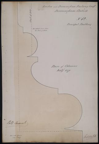
Drawing of Curzon Street Station, Birmingham (London & Birmingham Railway), showing section of the base of the principal building's columns, signed by Philip Hardwick, Grissell and Peto

Drawing of Curzon Street Station, Birmingham (London & Birmingham Railway), showing full scale elevation of the cornice over the entrance door of the Offices of Goods, signed by Philip Hardwick, Grissell and Peto
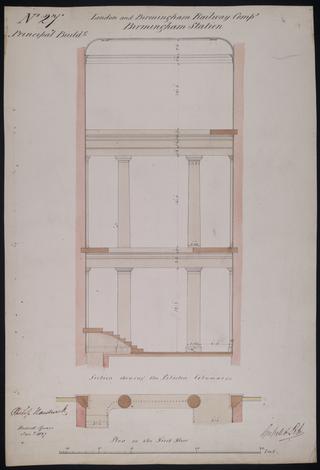
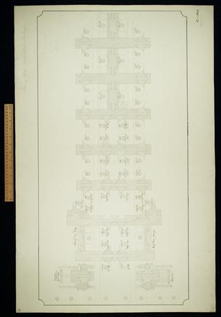
Drawing of Curzon Street Station, Birmingham (London & Birmingham Railway), showing section of principal building showing pilasters and columns along with a plan of the same area on first floor, signed by Philip Hardwick, Grissell and Peto

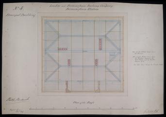
Drawing of Curzon Street Station, Birmingham (London & Birmingham Railway), showing plan of roofs and gutters at Birmingham Station with sectional drawings showing truss over stables and the truss over harness room

Drawing of Curzon Street Station, Birmingham (London & Birmingham Railway), showing section of the truss over the booking offices and colonade, section of the truss over the circular doors, plan of the roof gutters, trusses and binder for the celiing joists
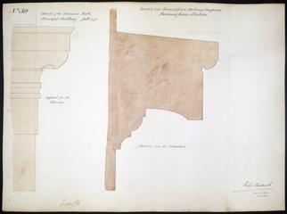
Drawing of Curzon Street Station, Birmingham (London & Birmingham Railway), showing details of the entrance to the principal building in a sectional drawing for the pilasters and cornice above signed by Philip Hardwick, Grissell and Peto
Drawing of Curzon Street Station, Birmingham (London & Birmingham Railway), showing details of roof including gutters, binders, trusses and lead work, signed by Philip Hardwick
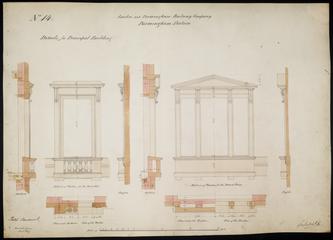
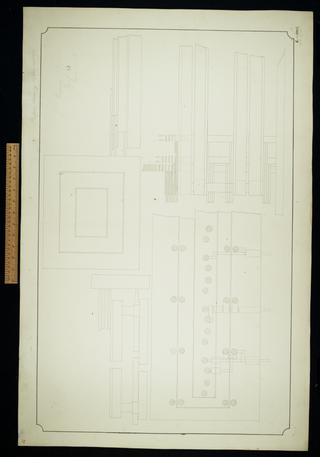
Drawing of Curzon Street Station, Birmingham (London & Birmingham Railway), showing exterior of the principal building's first floor and board room windows, giving section, profile and plan of each one, signed by Philip Hardwick, Grissell and Peto

Drawing of Curzon Street Station, Birmingham (London & Birmingham Railway), showing elevation of the flanks of the building, signed by Philip Hardwick of Grissell and Peto

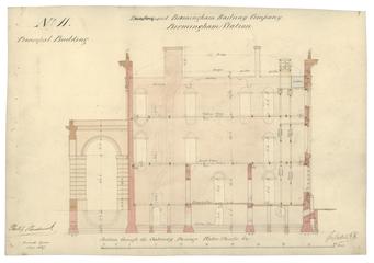
Drawing of Curzon Street Station, Birmingham (London & Birmingham Railway), showing section through Entrance and traffic office, signed by Philip Hardwick, Grissell and Peto

Drawing of Curzon Street Station, Birmingham (London & Birmingham Railway), showing section of the principal building's cornice and architrave, signed by Philip Hardwick, Grissell and Peto

Drawing of Curzon Street Station, Birmingham (London & Birmingham Railway), showing front elevation of the principal building, signed by Philip Hardwick, Grissell and Peto
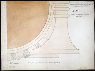
Drawing of Curzon Street Station, Birmingham (London & Birmingham Railway), showing plan of upper diameter of columns, approx. 1/4 of total surface represented, signed by Philip Hardwick, Grissell and Peto
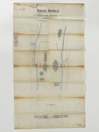
Temporary staging

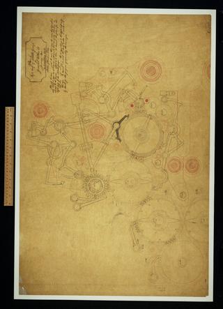
Untitled. [Operations for the Analytical Engine]
Letter from Robert Bill to Messrs Haynes and Douglas
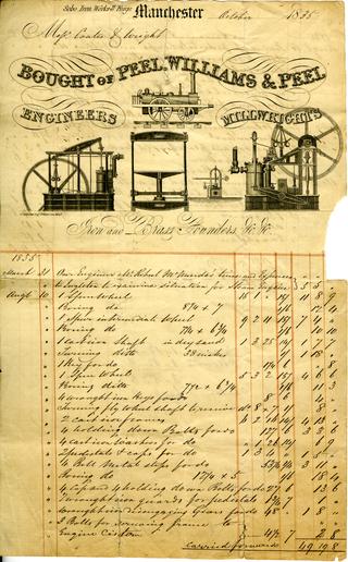
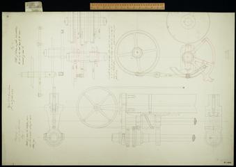
Invoice from Peel, Williams and Peel for a steam engine supplied to Messrs Coates and Wright
Copy [bill] London [to] Navy Commissrs./John Rennie, [for] Cast Iron Diving Bell, [pumps and machinery parts etc Reference to the 'Sheerness Diving Bell'. Bears note re the bell/Goodrich, and note from the Navy Office on verso]
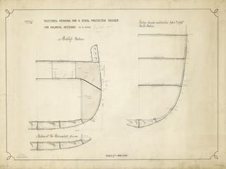
Drawing entitled 'Sectional Drawing for a Steel Protected Cruiser for Colonial Defence to be named'
Letter from Samuel Homfray to Messrs Haynes and Douglas
Stepping No. 1 on or in central wheels. Figure 1. Figure 2. Various unnumbered elevations, plans and details.
Letter from Messrs Blagrave and Walter to Messrs Haynes and Douglas and a copy of a letter Samuel Homfray to Messrs Blagrave and Walter
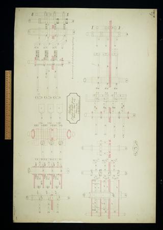
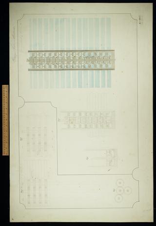
Elevation of parts of middle group drawn in plan on No. 127.
South East view of the Collegiate Church, Manchester

Print of the College at Manchester
Difference Engine index of parts.
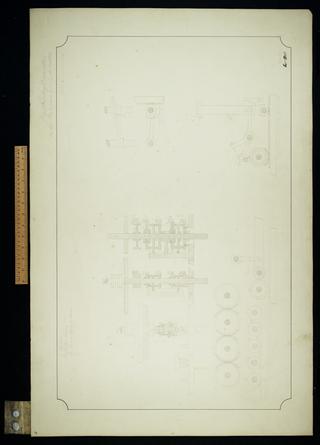
Digit counting apparatus on the two upper wheel selectors.
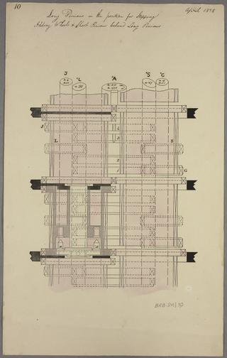
Long pinions in the position for stepping. Adding wheels and short pinions behind long wheels.
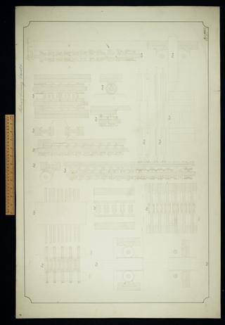
Carriage and racks in sections. Sheet 10.
Side and end elevation of feed motion with shade. Second revision.
Sections of framing and racks. Sheet 6.

Side and end elevation of feed motions. Showing the bands in different colours.
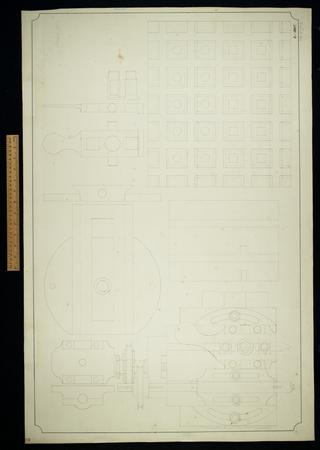
Reverse motion for cross planing.

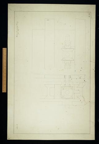
Back and end elevation of cross slide.

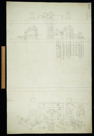
Side and end elevations of feed and driving apparatus
Small planing machine. Sheet 1.

Elevation and section of cross slide.
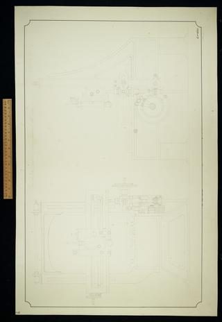
End and side elevation of Large Universal Machine.

Plan, elevation and section of cross slide.
Plan of left half of middle group for General Plan 28.

Plan of Large Universal Machine.
Untitled plan and elevation. Incomplete.
Plan of mill, table wheels and carriage. Sheet 31.

Untitled. A model of six cages was made from this drawing. Incomplete.
Platform raising apparatus. Sheet 33.

Drawing of the parts controlling the positioning and punching of the decimal point

Reduction of three simultaneous equations in three variables to two simultaneous equations in two variables

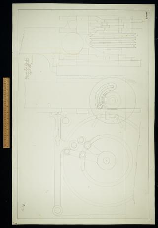
My Machine 1889 III Development of driving cams.
